The op amp circuit is a powerful took in modern circuit applications. You can put together basic op amp circuits to build mathematical models that predict complex, real-world behavior. Commercial op amps first entered the market as integrated circuits in the mid-1960s, and by the early 1970s, they dominated the active device market in analog circuits.
The op amp itself consists of a complex arrangement of transistors, diodes, resistors, and capacitors put together and built on a tiny silicon chip called an integrated circuit. You can model the op amp with simple equations with little concern for what’s going on inside the chip. You just need some basic knowledge of the constraints on the voltages and currents at the external terminals of the device.
How to draw op amp circuits
Unlike capacitors, inductors, and resistors, op amps require power to work. Op amps have the following five key terminals, shown here:
The positive terminal, called the noninverting input vP
The negative terminal, called the inverting input vN
The output terminal, resulting from the voltage applied between noninverting and inverting inputs: vO = A(vP – vN)
Positive and negative power supply terminals, usually labeled as +VCC and –VCC and required for the op amp to operate correctly
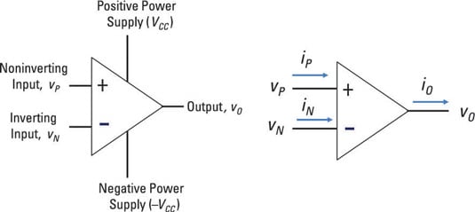
Although many op amps have more than five terminals, those terminals aren’t normally shown symbolically. Also, to reduce the clutter when you’re investigating an op amp circuit, the power supplies aren’t usually shown, either.
When the power supplies aren’t shown in a diagram of an op amp circuit, don’t forget that the power supplies provide upper and lower limits of the output voltage, restricting its voltage range. Barring otherworldly powers, you can’t get more power output than you supply.
The ideal op amp circuit and its transfer characteristics
You can model the op amp with a dependent source if you need accurate results, but the ideal op amp is good enough for most applications.
The op amp amplifies the difference between the two inputs, vP and vN, by a gain A to give you a voltage output vO:
The voltage gain A for an op amp is very large — greater than 105.
When the output voltage exceeds the supplied power, the op amp saturates. This means that the output is clipped or maxed out at the supplied voltages and can increase no further. When this happens, the op amp behavior is no longer linear but operates in the nonlinear region.
You can see this idea here; the left diagram shows the transfer characteristic, whereas the right diagram shows the ideal transfer characteristic of an op amp with an infinite gain. The graph shows three modes of operation for the op amp.
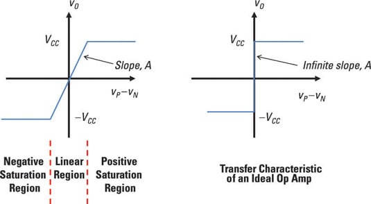
You have positive and negative saturated regions, showing the nonlinear and linear regions. If you want to make signals bigger, you need to operate in the linear region. You can describe the three regions mathematically as follows

To perform math functions (such as addition and subtraction), the op amp must work in linear mode. All op amp circuits shown here operate in the linear active region.
Model an op amp with a dependent source
If you need accurate results, you can model the op amp with a voltage-controlled dependent source, like the one shown here. This model consists of a large gain A, a large input resistance RI, and a small output resistance RO. The table shows ideal and typical values of these op amp properties.
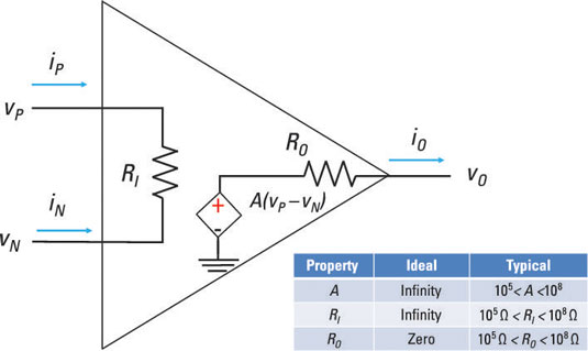
High amplification (or gain) makes the analysis simpler, allowing you not to worry about what’s going on inside the op amp. As long as the op amp has high gain, the op amp math circuits will work. High-input resistance draws little current from the input source circuit, increasing battery life for portable applications. Low- or no-output resistance delivers maximum voltage to the output load.
The dependent voltage-controlled current source is shown here as well. The output is restricted between the positive and negative voltages when the op amp is operating in the linear region.
Examine the essential equations for analyzing ideal op amp circuits
The ideal properties of an op amp produce two important equations:
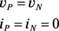
These equations make analyzing op amps a snap and provide you with valuable insight into circuit behavior. Why? Because feedback from the output terminals to one or both inputs ensures that vP and vN are equal.
To get the first constraint, consider that the linear region of an op amp is governed by when the output is restricted by the supply voltages as follows:

You can rearrange the equation to limit the input to vP – vN:
For an ideal op amp, the gain A is infinity, so the inequality becomes
Therefore, the ideal op amp (with infinite gain) must have this constraint:
An op amp with infinite gain will always have the noninverting and inverting voltages equal. This equation becomes useful when you analyze a number of op amp circuits, such as the op amp noninverter, inverter, summer, and subtractor.
The other important op amp equation takes a look at the input resistance RI. An ideal op amp has infinite resistance. This implies that no input currents can enter the op amp:
The equation says that the op amp input terminals act as open circuits.
You need to connect the output terminal to the inverting terminal to provide negative feedback in order to make the op amp work. If you connect the output to the positive side, you’re providing positive feedback, which isn’t good for linear operation. With positive feedback, the op amp would either saturate or cause its output to undergo oscillations.

