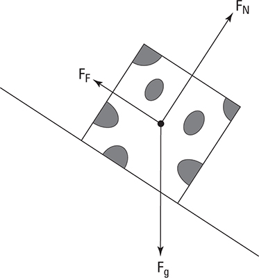
When you’re solving a physics problem with a bunch of forces pointing every which way, the easiest way to keep everything straight is to draw a free-body diagram. A free-body diagram is a diagram that depicts the directions and types of forces acting on an object. A Mona Lisa isn’t required — if you want to find the forces acting on a cow standing on the side of a hill, feel free to represent the cow as a square (you can add some spots to your square cow if you’re feeling particularly artistic).
The important part of the diagram is to draw all the forces acting on the object. A rather useful convention is to draw these vectors from the center of mass of the object, pointing away from that center. It’s also helpful (but not always possible when starting a problem) to draw vectors with lengths proportional to their magnitudes. A cow standing on a hill has three forces acting on it: the force of gravity, the normal force, and a frictional force. The gravitational force points down, the normal force is perpendicular to the hill, and friction points up the hill.

A free-body diagram makes it easy to use Newton’s second law,
The free-body diagram has all the forces and their directions, which is all the information you need to find the net force. The easiest way to add vectors is to add their components, so you’ll usually want to find the components of one or more of the force vectors in your free-body diagram. Great! You’ve already got a diagram showing which way each of your vectors points. You can draw the components of your forces on your free-body diagram by using dashed lines (or next to it if your diagram is getting crowded).
You can also use free-body diagrams to solve torque problems. When you’re solving a torque problem, you also need to keep track of what part of the object the forces acts upon. Torque is force times the lever arm, so if you’re dealing with angular motion, you can use your free-body diagram to figure out all the distances and angles you need to find the torque.


