The most recent main board to date is the Arduino Uno R3 (released in 2011). Think of it as the plain vanilla of Arduino boards. It’s a good and reliable workhorse suitable for a variety of projects. If you're just starting out, the Uno R3 is the board for you.
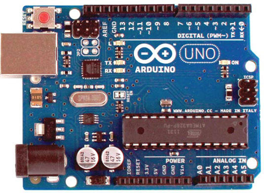
 The front of an Arduino Uno.
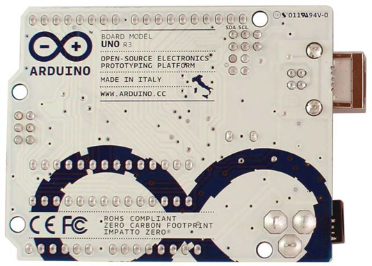
Check out the back of the Arduino Uno.
 The back of an Arduino Uno.
Uno is Italian for the number one, named for the release of version 1.0 of the Arduino software. Predecessors to this release had a variety of names, such as Serial, NG, Diecimila (10,000 in Italian, to mark that 10,000 boards had been sold), and Duemilanove (2009 in Italian, the release date of the board); the Uno has ushered in some much needed order to the naming of the boards. R3 relates to the revision of the features on the board, which includes updates, refinements, and fixes. In this case, it is the third revision.
The Brains of the Arduino Uno: ATmega328P microcontroller chip
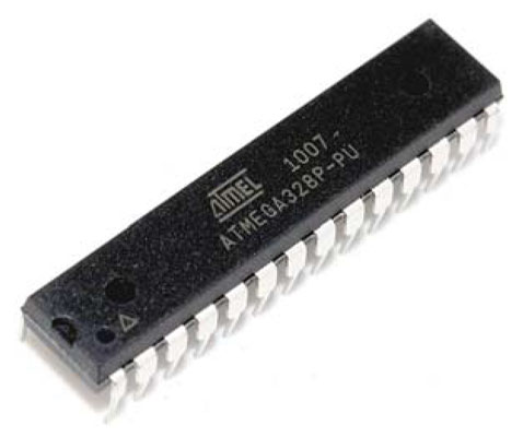
You can think of the microcontroller chip itself as the brains of the board. The chip used in the Arduino Uno is the ATmega328P, made by Atmel. It’s the large, black component in the center of the board. This chip is known as an integrated circuit, or IC. It sits in a socket; if you were to remove it. An ATmega328P microcontroller all by itself.
This same chip can come in different forms, referred to as packages. The one in an Arduino Uno is in a plated-through hole, or PTH, package, named because of the way it makes contact with the board. Another variation you may find is the Arduino Uno SMD, or surface mount device, package, which is mounted on the surface of the board rather than in holes that go through it. This chip is much smaller, but it is not replaceable, whereas the PTH chip is. Apart from that, it functions exactly the same as the PTH and differs only in looks.
Header sockets in the Arduino Uno
The microcontroller socket connects all the legs of the ATmega328 microcontroller chip to other sockets, referred to as header sockets, which are arranged around the edge of the board and are labeled for ease of use. These black sockets are divided into three main groups: digital pins, analog input pins, and power pins.All these pins transfer a voltage, which can be either sent as output or received as an input. Why are these pins important? They allow you to connect additional circuitry to the board quickly and easily when prototyping with a breadboard and to design additional boards, called shields, that fit neatly on top of your Arduino board.
This same process of sending and receiving electrical signals is going on inside modern computers. But because they are so advanced and refined compared to a humble Arduino, it is difficult to directly link a computer accustomed to digital signals (0s and 1s) to an electronic circuit that deals with a range of voltages (0v to 5v in the ATmega328P’s case).
The Arduino is special because it can interpret these electric signals and convert them to digital signals that your computer can understand — and vice versa. It also enables you to write a program using software on a conventional computer that the Arduino IDE (integrated development environment) converts or compiles to electrical signals that your circuit can understand.
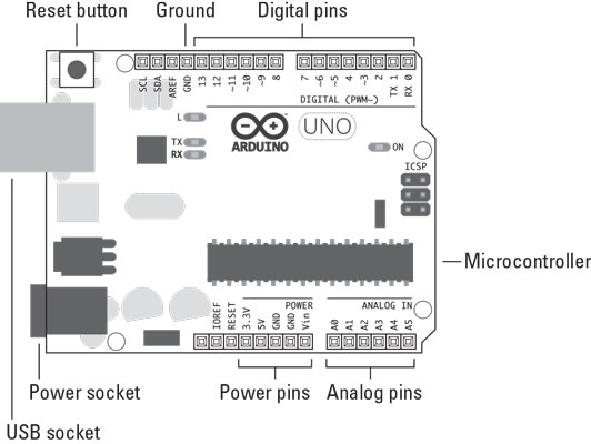
 An Arduino Uno with all the important parts labeled.
By bridging this gap, it is possible to use a conventional computer's benefits — ease of use, user-friendly interfaces, and code that is easy for humans to understand — to control a wide range of electronic circuits and even give them complex behaviors with relative ease.
Arduino Uno: Digital pins
You use digital pins to send and receive digital signals. Digital implies that the pins have two states: off or on. In electrical terms, these states translate to a value of 0 or 5 volts, but no values in between.Arduino Uno: Analog in pins
You use analog in pins to receive an analog value. An analog value is taken from a range of values. In this case, the range is the same 0V to 5V as with the digital pins, but the value can be at any point — 0.1, 0.2, 0.3, and so on.What about analog out for the Arduino Uno?
The shrewd ones among you may have noticed that there seem to be no analog out pins. In fact, the analog out pins are there, but they’re hidden among the digital pins marked as PWM using the ~ symbol. PWM stands for pulse-width modulation, which is a technique you can use to give the impression of an analog output using digital pins. The ~ symbol appears next to digital pins 3, 5, 6, 9, 10, and 11, showing that you have six pins that are capable of PWM.Power pins in the Arduino Uno
You use the power pins to distribute power to inputs and outputs wherever power is needed.Vin, which stands for voltage in, can be used to supply a voltage (V) equal to the one supplied by the external supply jack (for example, 12V). You can also use this pin to supply power to the Arduino from another source.
GND marks the ground pins, which are essential to complete circuits. There is also a third ground by pin 13. All these pins are linked and share the same (called common) ground.
You can use 5V or 3.3V to supply a 5-volt or 3.3-volt power supply, respectively, to components or circuits.
USB socket on the Arduino Uno
To tell the microcontroller on the Arduino board what to do, you need to send a program to it. On the Uno, you send programs primarily by a USB connection. The large, metallic socket is a USB port for a USB A-B cable. This cable is similar to the one used on your home printer or scanner, so you may find a few around the house that can serve as handy spares. The Arduino uses the USB both for power and to transfer data. Using a USB cable is perfect for low-power applications and when data is being sent to or received from a computer.Power socket on the Arduino Uno
Next to the USB socket is another socket; this one is for power. This socket allows you to power your Arduino from an external power supply. The supply could be from an AC-to-DC adaptor (similar to those used on other consumer electronics), a battery, or even a solar panel.The connector needed is a 2.1 mm center positive plug. Center positive simply means that the plug has an outside and an inside that fit the socket and that the inside of the plug must be positive. You should be able to find this plug among the standard connectors that come with most power supplies; otherwise, you can buy the connector and attach it to bare wires.
If you connect a power supply that is the opposite (center negative), it is known as having a reverse polarity. Components on the Arduino Uno will resist your attempts to send voltage the wrong way around the board, but those components can melt in the process of saving your board, depending on how much power you're sending and how long it takes you to notice the burning smell! If you reverse the polarity when using the Vin, 5V, or 3.3V pins, you bypass this protection and almost instantly destroy several parts of your board and the ATmega328P chip.
The recommended voltage for the Uno board is 7–12V. If you supply too little power, your board might not function correctly. Or if you provide too much power, your board might overheat and potentially be damaged.LEDs
LEDs come in a variety of shapes and sizes and are found in almost every modern piece of consumer electronics, from bike lights to TVs to washing machines.The components are tiny. The Uno board has four LEDs (light-emitting diodes) labeled L, RX, TX, and ON. An LED is a component that produces light when electrical current flows through it.
These four LEDs are used to indicate activity on the board, as follows:
- ON is green and signifies that your Arduino is powered.
- RX and TX tell you that data is being received or transmitted by the board.
- L is a special LED connected to digital pin 13. It is great for testing to see whether your board is functioning as you want.
- Your USB cable is plugged in
- Your USB port is working — try another device in the port
- Your cable is working — try another cable, if possible
Reset button on the Arduino Uno
The Uno board also has a button next to the USB socket called the reset button. It resets the program on the Arduino or stops it completely when held down for a time. Connecting a wire between GND and the reset pin, which is located next to the 3.3V, achieves the same results.The board has many other components, all of which perform important jobs, but the ones described here are the key ones for you to know as you get started.


