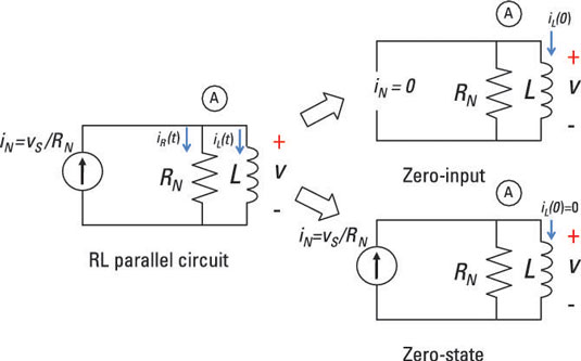
Analyzing such a parallel RL circuit, like the one shown here, follows the same process as analyzing an RC series circuit. So if you are familiar with that procedure, this should be a breeze.

If your RL parallel circuit has an inductor connected with a network of resistors rather than a single resistor, you can use the same approach to analyze the circuit. But you have to find the Norton equivalent first, reducing the resistor network to a single resistor in parallel with a single current source.
Start with the simple RL parallel circuit
Because the resistor and inductor are connected in parallel in the example, they must have the same voltage v(t). The resistor current iR(t) is based on Ohm’s law:![]()
The element constraint for an inductor is given as
![]()
where i(t) is the inductor current and L is the inductance.
You need a changing current to generate voltage across an inductor. If the inductor current doesn’t change, there’s no inductor voltage, which implies a short circuit.
Now substitute v(t) = Ldi(t)/dt into Ohm’s law because you have the same voltage across the resistor and inductor:![]()
Kirchhoff’s current law (KCL) says the incoming currents are equal to the outgoing currents at a node. Use KCL at Node A of the sample circuit to get iN(t) = iR(t) =i(t).
Substitute iR(t) into the KCL equation to give you
![]()
The RL parallel circuit is a first-order circuit because it’s described by a first-order differential equation, where the unknown variable is the inductor current i(t). A circuit containing a single equivalent inductor and an equivalent resistor is a first-order circuit.
Knowing the inductor current gives you the magnetic energy stored in an inductor.
In general, the inductor current is referred to as a state variable because the inductor current describes the behavior of the circuit.
Calculate the zero-input response for an RL parallel circuit
Here is how the RL parallel circuit is split up into two problems: the zero-input response and the zero-state response. Here, you’ll start by analyzing the zero-input response.
To simplify matters, you set the input source (or forcing function) equal to 0: iN(t) = 0 amps. This means no input current for all time — a big, fat zero. The first-order differential equation reduces to
![]()
For an input source of no current, the inductor current iZI is called a zero-input response. No external forces are acting on the circuit except for its initial state (or inductor current, in this case). The output is due to some initial inductor current I0 at time t = 0.
You make a reasonable guess at the solution (the natural exponential function!) and substitute your guess into the RL first-order differential equation. Assume the inductor current and solution to be
iZI(t) = BektThis is a reasonable guess because the time derivative of an exponential is also an exponential. Like a good friend, the exponential function won’t let you down when solving these differential equations.
You determine the constants B and k next. Substitute your guess iZI(t) = Bekt into the differential equation:
![]()
Replacing iZI(t) with Bekt and doing some math gives you the following:

You have the characteristic equation after factoring out Bekt:
![]()
The characteristic equation gives you an algebraic problem to solve for the constant k:

Use k = –R/L and the initial inductor current I0 at t = 0. This implies that B = I0, so the zero-input response iZI(t) gives you the following:
![]()
The constant L/R is called the time constant. The time constant provides a measure of how long an inductor current takes to go to 0 or change from one state to another.
To analyze the RL parallel circuit further, you must calculate the circuit’s zero-state response, and then add that result to the zero-input response to find the total response for the circuit.


