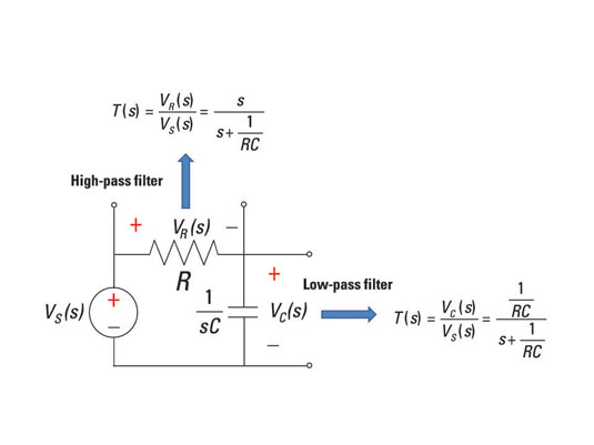
With simple RC circuits, you can build first-order RC low-pass (LPF) and high-pass filters (HPF). These simple circuits can give you a foundational understanding of how filters work so you can build more-complex filters.
First-order RC low-pass filter (LPF)
Here's an RC series circuit — a circuit with a resistor and capacitor connected in series. You can get a low-pass filter by forming a transfer function as the ratio of the capacitor voltage VC(s) to the voltage source VS(s).

You start with the voltage divider equation:
The transfer function T(s) equals VC(s)/VS(s). With some algebra (including multiplying the numerator and denominator by s/R), you get a transfer function that looks like a low-pass filter:
You have a pole or corner (cutoff) frequency at s = –1/(RC), and you have a DC gain of 1 at s = 0. The frequency response starts at s = 0 with a flat gain of 0 dB. When it hits 1/(RC), the frequency response rolls off with a slope of –20 dB/decade.
For circuits with only passive devices, you never get a gain greater than 1.
First-order RC high-pass filter (HPF)
To form a high-pass filter, you can use the same resistor and capacitor connected in series shown earlier, but this time, you measure the resistor voltage VR(s). You start with the voltage divider equation for the voltage across the resistor VR(s):

With some algebraic manipulation (including multiplying the numerator and denominator by s/R), you can find the transfer function T(s) = VR(s)/VS(s) of a high-pass filter:
You have a zero at s = 0 and a pole at s = –1/(RC ). You start off the frequency response with a zero with a positive slope of 20 dB/decade, and then the response flattens out starting at 1/(RC). You have a constant gain of 1 at high frequencies (or at infinity) starting at the pole frequency.


