The Raspberry Pi is the perfect platform to do physical computing with Python because it has a multiscreen environment, lots of RAM and storage to play with and all the tools to build fun projects.
A huge and powerful feature of the Raspberry Pi is the row of GPIO (general purpose input-output) pins along the top of the Raspberry Pi. It is a 40-pin header into which you can plug a large number of sensors and controllers to do amazing things to expand your Raspberry Pi.
GPIO pins on the Raspberry Pi
GPIO pins can be designated (using Python software) as input or output pins and used for many different purposes. There are two 5V power pins, two 3.3V power pins and a number of ground pins that have fixed uses. The functions of the Raspberry Pi GPIO pins.
An GPIO pin output pin “outputs” a 1 or a 0 from the computer to the pin. Basically, A “1” is 3.3V and a “0” is 0V. You can think of them just as 1s and 0s.
GPIO Python libraries
There are a number of GPIO Python libraries that are usable for building projects. A good one to use is the gpiozero library that is installed on all Raspberry Pi desktop software releases. Check out the library documentation and installation instructions (if needed).Now let’s jump into the “Hello World” physical computing project with our Raspberry Pi.
The hardware for “Hello World” on the Raspberry Pi
To do this project, you’ll need some hardware. Because these instructions involve using Grove connectors, let's get the two pieces of Grove hardware that you need for this project:- Pi2Grover: This converts the Raspberry Pi GPIO pin header to Grove connectors (ease of use and can’t reverse the power pins!). You can buy this either at shop.switchdoc.com or at Amazon.com. You can get $5.00 off the Pi2Grover board at shop.switchdoc.com by using the discount code PI2DUMMIES at checkout.
 The Pi2Grover board.
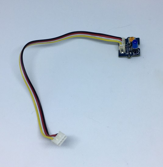
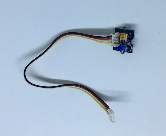
 - Grove blue LED: A Grove blue LED module including Grove cable. You can buy this on shop.switchdoc.com or on amazon.com.
 The Grove blue LED.
 The Grove cable (included with the LED).
How to assemble the Raspberry Pi’s hardware
For a number of you readers, this will be the first time you have ever assembled a physical computer-based product. because of this, we’ll give you the step-by-step process:- Identify the Pi2Grover board.
- Making sure you align the pins correctly gently press the Pi2Grover Board (Part A) onto the 40 pin GPIO connector on the Raspberry Pi.
 Aligning the Pi2Grover board on the Raspberry Pi.
 - Gently finish pushing the Pi2Grover (Part A) onto the Raspberry Pi GPIO pins, making sure the pins are aligned. There will be no pins showing on either end and make sure no pins on the Raspberry Pi are bent.
 The installed Pi2Grover board.
 - Plug one end of the Grove cable into the Grove blue LED board.
 A Grove cable plugged into the Grove blue LED board.
 - If your blue LED is not plugged into the Grove blue LED board, then plug in the LED with the flat side aligned with the flat side of the outline on the board.
 The LED aligned with the outline on the board.
 - Plug the other end of the Grove cable into the slot marked D12/D13 on the Pi2Grover board.You are now finished assembling the hardware. Now it’s time for the Python software.
 The completed “Hello World” project.


